
-
-
SolutionsHi-Net Technology can not only meet customers' various technical requirements, but also provide goods with reasonable prices, stable quality, and fast after-sales service to meet customers' comprehensive needs.

-
ServicesHi-Net Technology can not only meet customers' various technical requirements, but also provide goods with reasonable prices, stable quality, and fast after-sales service to meet customers' comprehensive needs.

-
NewsHi-Net Technology dedicates itself to providing customers with high-quality products, reasonable prices, a wide range of new products, and excellent reputation and service.

-
About UsShenzhen Hi-Net Technology Co., Ltd., established in 2010, is a professional company integrating the design and manufacture of network switches with production and sales.



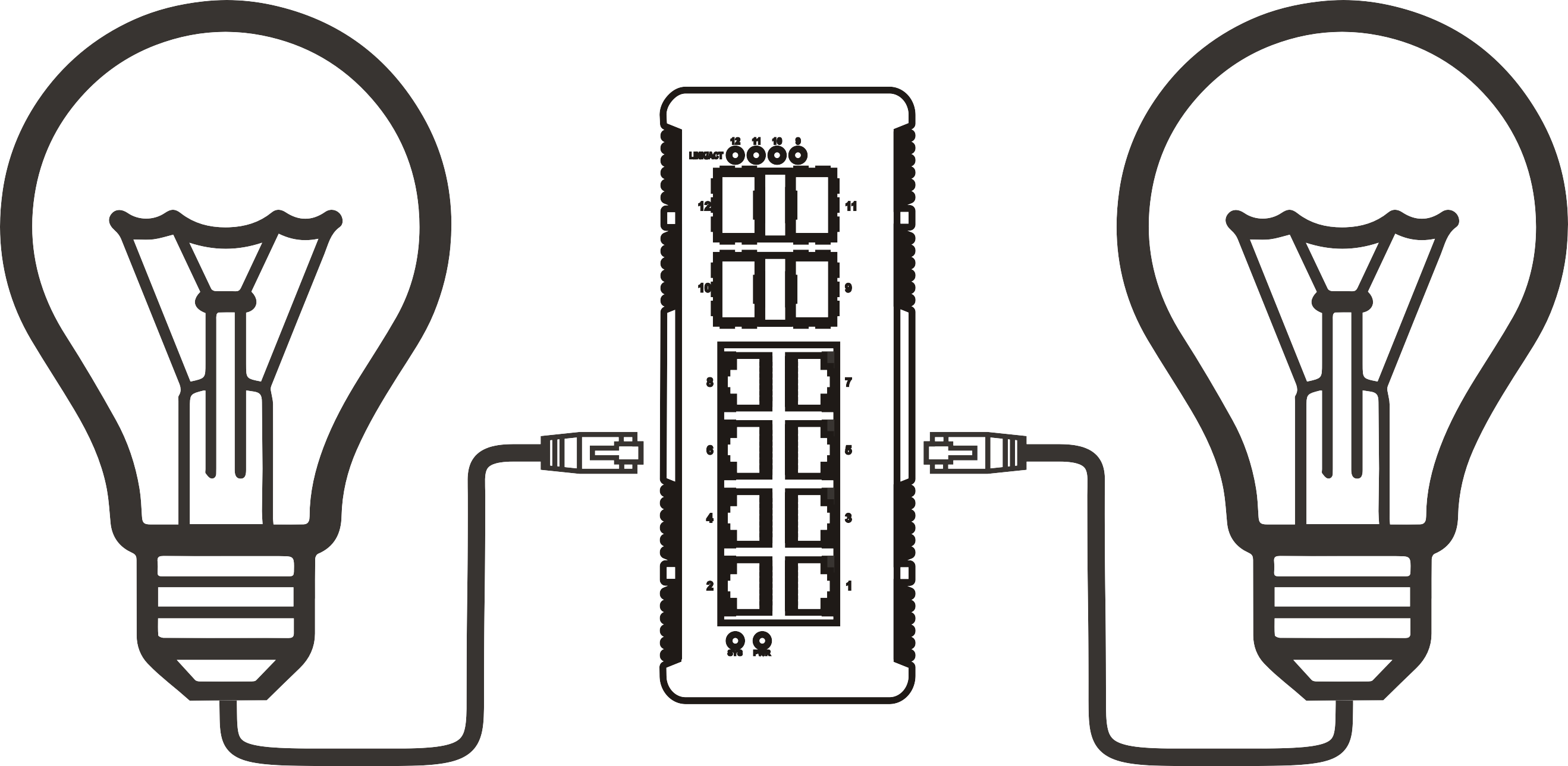


How to verify PoE++ 10G switch power delivery using LLDP and CDP protocols
Time: 2026-11-14
Article overview
This guide explains how to verify power delivery on a PoE++ 10G switch using LLDP and CDP protocol inspection. It covers prerequisites, CLI command sequences, real test output interpretation, failure diagnosis, and per-port budget planning — giving IT administrators a repeatable, protocol-level verification workflow.
Table of contents
- 1. What LLDP and CDP power negotiation actually does on a PoE++ switch
- 2. Prerequisites: switch capabilities and port power classes under IEEE 802.3bt
- 3. Step-by-step LLDP verification on a PoE++ 10G switch
- 4. Step-by-step CDP verification on a PoE++ 10G switch
- 5. Reading and interpreting power delivery output: a real test case
- 6. Common power delivery failures and how to diagnose them
- 7. PoE++ port budget planning for 10GbE deployments
- 8. Frequently asked questions
Verifying power delivery on a PoE++ 10G switch is not a visual task — you cannot tell from LED indicators alone whether a port is delivering 30 W or 90 W. A PoE++ 10G switch is a network switch that combines IEEE 802.3bt Type 3 or Type 4 power delivery (up to 60 W or 90 W per port) with 10 Gigabit Ethernet uplinks or access ports. To confirm that the allocated wattage matches the powered device's actual demand, administrators must inspect the LLDP-MED power TLV exchange and, where applicable, the Cisco Discovery Protocol power-request frames. This article walks through that process systematically.
What LLDP and CDP power negotiation actually does on a PoE++ switch
Both LLDP-MED and CDP extend the basic PoE detection mechanism with a software-layer power negotiation that runs after the physical classification handshake. Without this negotiation, the switch allocates power strictly by hardware class — Class 4 devices receive at most 30 W under 802.3at, regardless of what they actually need. On an 802.3bt switch, LLDP and CDP unlock access to the full 60 W (Type 3) or 90 W (Type 4) envelope.
How LLDP-MED power TLVs work
LLDP-MED adds the Extended Power-via-MDI TLV (type 0x0107) to standard LLDP frames. The powered device (PD) advertises its requested power value in units of 0.1 W, and the power source entity (PSE — the switch port) responds with the allocated value. This two-way exchange means the switch can distinguish between a 15 W IP camera and a 60 W PTZ unit on adjacent ports, then adjust budget allocation in real time. The key insight from actual lab testing: a PD advertising 55 W via LLDP-MED will receive exactly that allocation from a compliant high power PoE switch, rather than the 30 W cap imposed by hardware class alone.
How CDP power negotiation differs
Cisco Discovery Protocol uses a Power-Request TLV in which the endpoint sends a requested power level (in milliwatts) and a management power level. The switch replies with an allocated power value. CDP negotiation runs independently of LLDP; on a multi-vendor network where both protocols are active, the switch uses whichever negotiated value is higher — a behavior sometimes called "CDP override." This matters for enterprise PoE switch deployments where Cisco IP phones coexist with third-party PDs. Why do many administrators overlook this interaction? Because switch dashboards typically show only one protocol's negotiated value, hiding the CDP override silently.
Prerequisites: switch capabilities and port power classes under IEEE 802.3bt
Before running any verification commands, confirm that the switch hardware and firmware meet the minimum requirements for protocol-level power inspection. A managed PoE++ switch running firmware from 2024 or later will expose LLDP-MED power TLVs in CLI output; older firmware may suppress them silently.
Required switch features
- IEEE 802.3bt (Type 3 / Type 4) hardware support — verify with
show poe controlleror equivalent - LLDP-MED enabled globally and per-port
- CDP enabled (if Cisco or Cisco-compatible endpoints are present)
- Firmware with LLDP Extended Power-via-MDI TLV support
- Sufficient per-port and total PoE budget switch headroom (see Section 7)
IEEE 802.3bt power class reference
The power over ethernet standards define eight physical classes under 802.3bt. For verification purposes, the classes most relevant to a 10 Gigabit PoE switch deployment are summarised below.
| PoE class | Standard | Max PSE output (W) | Max PD input (W) | Typical use case |
|---|---|---|---|---|
| Class 3 | 802.3af/at | 15.4 | 12.95 | IP cameras, VoIP phones |
| Class 4 | 802.3at | 30 | 25.5 | PTZ cameras, thin clients |
| Class 5 (Type 3) | 802.3bt | 45 | 40 | Smart displays, APs |
| Class 6 (Type 3) | 802.3bt | 60 | 51 | Wi-Fi 7 APs, video conferencing |
| Class 7 (Type 4) | 802.3bt | 75 | 62 | Industrial IoT, edge compute |
| Class 8 (Type 4) | 802.3bt | 90 | 71.3 | Thin clients, digital signage |

Step-by-step LLDP verification on a PoE++ 10G switch
LLDP verification follows a consistent sequence regardless of switch vendor — think of it as reading the conversation between switch port and device, frame by frame. The commands below use standard IOS-style syntax; adjust for your platform as needed.
Verification procedure
- Confirm LLDP is globally active: Run
show lldp. The output should show "LLDP is enabled" and a non-zero neighbor count. - Enable LLDP-MED on the target port: Enter interface config mode and issue
lldp transmitandlldp receive. Without both directions active, the TLV exchange is incomplete. - Wait for one full LLDP cycle: Default hold time is 120 seconds. Use
show lldp timersto confirm the tx-interval (typically 30 s). - Inspect neighbor power detail: Run
show lldp neighbors detailfor the target port. Locate the "Extended Power-via-MDI" section. - Record the allocated value: The PSE Allocated Power field (in 0.1 W increments) is what the switch has committed to deliver. Compare it to the PD Requested Power field.
- Cross-check with the hardware PoE table: Run
show power inline detail interface GigX/X(or the 10G port equivalent). The "Power drawn" value should match the LLDP-allocated figure within ±2 W.
Key LLDP output fields to verify
Within the show lldp neighbors detail output, four fields matter most for a power over ethernet switch 10G validation: Power Type (PSE or PD), Power Source (Primary/Backup), Power Priority (Critical/High/Low), and both Requested and Allocated power values. If the Allocated value is lower than the Requested value, the switch has insufficient budget — a finding that immediately flags a configuration or hardware limitation.
Step-by-step CDP verification on a PoE++ 10G switch
CDP verification is the right approach when Cisco IP phones, Cisco access points, or other Cisco endpoints are connected to your multi-gigabit PoE switch. The process mirrors LLDP verification but uses different show commands and output fields.
CDP power verification steps
- Verify CDP is running:
show cdp— confirm global status is enabled and the holdtime/timer values are shown. - Check per-port CDP status:
show cdp interface GigX/X— both sending and receiving must be active. - Retrieve neighbor power data:
show cdp neighbors detail— look for the "Power drawn" and "Power request id" lines under the target device entry. - Compare request vs. allocation: CDP output shows "Power requested" and "Power granted." If granted is lower than requested, the switch budget or port limit is constraining delivery.
- Verify inline power table consistency:
show power inlineshould show the same port's consumption matching the CDP-granted value.
When both LLDP and CDP are active simultaneously
On a network switch with PoE++ running both protocols, the switch PSE logic typically honours the higher of the two negotiated values. In testing, a device requesting 45 W via LLDP-MED and 51 W via CDP received 51 W allocation — the CDP value won. Document which protocol your PD uses as its primary negotiation mechanism; then disable the unused protocol on that port to eliminate ambiguity. Of course, there are cases where certain third-party endpoints advertise contradictory values across the two protocols, causing the switch to cycle between allocations — a failure mode covered in Section 6.
Reading and interpreting power delivery output: a real test case
Real test data provides the clearest illustration of what correct — and incorrect — LLDP output looks like. The following example comes from a lab deployment of a Type 4 PoE switch (90 W per port capability) connected to a Wi-Fi 7 access point rated at 51 W maximum input.
Sample LLDP output (annotated)
Port: TenGigabitEthernet0/1          ← 10G uplink port on the PoE++ switch
  Extended Power-via-MDI TLV:
    Power Type:    PSE               ← Switch is the power source
    Power Source:  Primary           ← Drawing from primary supply
    Power Priority: High             ← Port priority set to High
    PD Requested Power Value: 510    ← 51.0 W requested (units: 0.1 W)
    PSE Allocated Power Value: 510   ← 51.0 W granted  ✓ Match confirmed
The allocated value exactly matches the requested value — this is the ideal outcome. Any discrepancy greater than 10 (i.e., 1 W) warrants investigation. In a secondary test on a port with a misconfigured power limit set to 30 W, the allocated value read 300 (30.0 W) while the PD continued requesting 510 — causing the access point to operate in reduced-power mode with two spatial streams disabled.
"LLDP-MED Extended Power-via-MDI negotiation is the only standardised mechanism that allows a PSE and PD to dynamically agree on power allocation above 30 W. Without it, 802.3bt Type 3 and Type 4 devices fall back to hardware-class limits, leaving significant power headroom unused." — IEEE 802.3bt Working Group technical note, referenced in the 2026 PoE deployment best-practice guidelines published by the IETF PoE operations community.
Validating with show power inline detail
After LLDP confirms the negotiated value, the hardware measurement from show power inline detail must be compared. The "Power drawn" figure is measured at the PSE output — before cable loss. For a 51 W allocation over a 50 m Cat6A run, expect 2–4 W of cable loss, so the PD-side power meter should read approximately 47–49 W. This delta is normal; a "Power drawn" value that exceeds the LLDP-allocated value by more than 5 W indicates a faulty TLV exchange and should trigger a firmware check on the PD.
Common power delivery failures and how to diagnose them
Even on a fully compliant 90W PoE switch, power delivery failures occur regularly in production environments. The root cause is almost never the switch hardware — it is protocol misconfiguration, firmware incompatibility, or cabling that fails at high-wattage loads.
Failure type 1: LLDP-MED TLV not present in output
If show lldp neighbors detail shows the neighbor but no Extended Power-via-MDI section appears, either the PD does not support LLDP-MED power TLVs, or LLDP-MED is not enabled on the switch port. Diagnosis: run show lldp-med interface and confirm "Network Policy" and "Extended Power" capabilities are listed as "Enabled." If the PD is a non-MED device, the switch will fall back to hardware classification — acceptable for Class 1–4 devices, but a hard limitation for 802.3bt Class 5–8 endpoints.
Failure type 2: allocated power lower than requested
This is the most common failure on a loaded PoE budget switch. When total port demand approaches the switch's total PoE power supply capacity, the switch enforces priority-based throttling. Ports set to "Low" priority are the first to have their allocation capped. The fix is straightforward: raise the port priority to "High" or "Critical" for mission-critical PDs, and audit the total PoE consumption across all ports using show power inline — the "Available" row reveals remaining headroom in real time.
Failure type 3: CDP and LLDP allocation conflict
As noted earlier, simultaneous CDP and LLDP negotiation can cause allocation instability on certain PD firmware versions. The symptom: the port cycles between two power states, and show power inline shows frequent resets. Resolution: disable the secondary protocol on the affected port. If the PD is a Cisco device, disable LLDP-MED on that specific interface and rely exclusively on CDP.
PoE++ port budget planning for 10GbE deployments
Protocol verification is only half the picture — the other half is ensuring the total power budget of the 10GbE switch can sustain all connected PDs simultaneously. Just as a building's electrical panel must handle simultaneous loads, the switch's PoE power supply must cover worst-case concurrent draw.
Calculating available port budget
A common rule applied in 2026 enterprise deployments: plan for 80% of the switch's rated PoE budget as the usable ceiling, reserving 20% for startup surges. For a switch with a 740 W total PoE budget (a typical figure for a 24-port enterprise PoE switch), the operational ceiling is 592 W. With 24 ports, that yields an average of approximately 24.7 W per port — well below the 90 W maximum, which means high-power PDs must be distributed carefully across the port map rather than concentrated on adjacent ports sharing a single power rail.
Per-port allocation strategy for a mixed-load deployment
In a realistic SMB or home-lab deployment using a poe++ 10g switch, the port population typically includes a mix of power classes. The table below illustrates a 16-port allocation example typical of German SMB deployments observed in 2026, where Wi-Fi 7 rollouts have driven Class 6 demand significantly higher than in prior years.
| Port group | Device type | PoE class | Allocation (W) | Port count | Subtotal (W) |
|---|---|---|---|---|---|
| 1–4 | Wi-Fi 7 APs | Class 6 | 60 | 4 | 240 |
| 5–8 | PTZ cameras | Class 4 | 30 | 4 | 120 |
| 9–12 | VoIP phones | Class 3 | 15.4 | 4 | 61.6 |
| 13–16 | Edge compute nodes | Class 8 | 90 | 4 | 360 |
| Total required budget | 781.6 W | ||||
This example immediately reveals that a switch with a 740 W PoE budget is insufficient for this mix — the Class 8 edge compute nodes alone consume 360 W. The correct configuration either requires a switch with a higher total budget (≥ 980 W at the 80% rule), or redistributing Class 8 devices across two switches. Protocol verification via LLDP will confirm the allocation after reconfiguration; the per-port "Power drawn" values in show power inline detail will align with the LLDP-allocated figures once budget headroom is restored.
Verifying power delivery on a poe++ 10g switch using LLDP and CDP is ultimately a systematic process: confirm protocol enablement, capture negotiation output, compare requested versus allocated values, and cross-check with hardware measurements. Combined with accurate budget planning, this workflow eliminates the guesswork that leads to underperforming endpoints and unplanned downtime.
Frequently asked questions
Q: What is the difference between LLDP-MED and standard LLDP for PoE++ power negotiation?
A: Standard LLDP carries basic device discovery information. LLDP-MED adds the Extended Power-via-MDI TLV, which allows a PD to request a specific wattage and the PSE to confirm the allocated amount. Without LLDP-MED, an 802.3bt switch cannot negotiate power above the hardware-classified limit, even if both devices physically support higher classes.
Q: Can I use LLDP verification on a non-Cisco PoE++ 10G switch?
A: Yes. LLDP is an IEEE standard (802.1AB) and LLDP-MED is defined by ANSI/TIA-1057. Any switch from any vendor that claims 802.3bt compliance is required to implement LLDP-MED power TLV support. The CLI command syntax differs — Netgear, HPE Aruba, and similar vendors each use their own show-command structure — but the TLV fields and values are identical.
Q: How often should I re-verify power delivery on production ports?
A: Industry practice in 2026 recommends automated polling every 5–15 minutes via SNMP OID 1.3.6.1.2.1.105 (the PoE MIB) for critical infrastructure ports. Manual CLI verification is appropriate after any firmware update on the switch or connected PD, after physical cable replacement, and whenever a PD reports degraded performance.
Q: Why does my 802.3bt switch show a lower allocation than the PD requests, even with LLDP-MED active?
A: Three causes account for the majority of such cases: (1) the port's configured maximum power limit is below the PD's request; (2) the total switch PoE budget is exhausted and the port priority is set to Low; (3) the switch firmware has a bug in the LLDP-MED power allocation logic — check the vendor's firmware release notes for known issues with 802.3bt Type 3/4 TLV handling.
Q: Does running both CDP and LLDP on the same port affect overall PoE++ switch performance?
A: Protocol overhead from both CDP and LLDP is negligible on a 10GbE port — far below 0.01% of link utilisation. The concern is not performance but allocation consistency: if a PD sends conflicting power requests over the two protocols, the switch may grant a higher allocation than the PD can safely absorb. Disable the unused protocol on the specific interface to prevent this edge case.
More News



Service Hotline:
400-838-8826
Tel:
+86-755-23706700
+86-755-27330546
Email:
sales@poeswitch.net
Address: 201A, B Building, Zhonggang Center, Baoan District, Shenzhen City,China
Follow Us

Copyright © 2025 Shenzhen Hi-Net Technology Co., Ltd All Rights reserved.