
-
-
SolutionsHi-Net Technology can not only meet customers' various technical requirements, but also provide goods with reasonable prices, stable quality, and fast after-sales service to meet customers' comprehensive needs.

-
ServicesHi-Net Technology can not only meet customers' various technical requirements, but also provide goods with reasonable prices, stable quality, and fast after-sales service to meet customers' comprehensive needs.

-
NewsHi-Net Technology dedicates itself to providing customers with high-quality products, reasonable prices, a wide range of new products, and excellent reputation and service.

-
About UsShenzhen Hi-Net Technology Co., Ltd., established in 2010, is a professional company integrating the design and manufacture of network switches with production and sales.



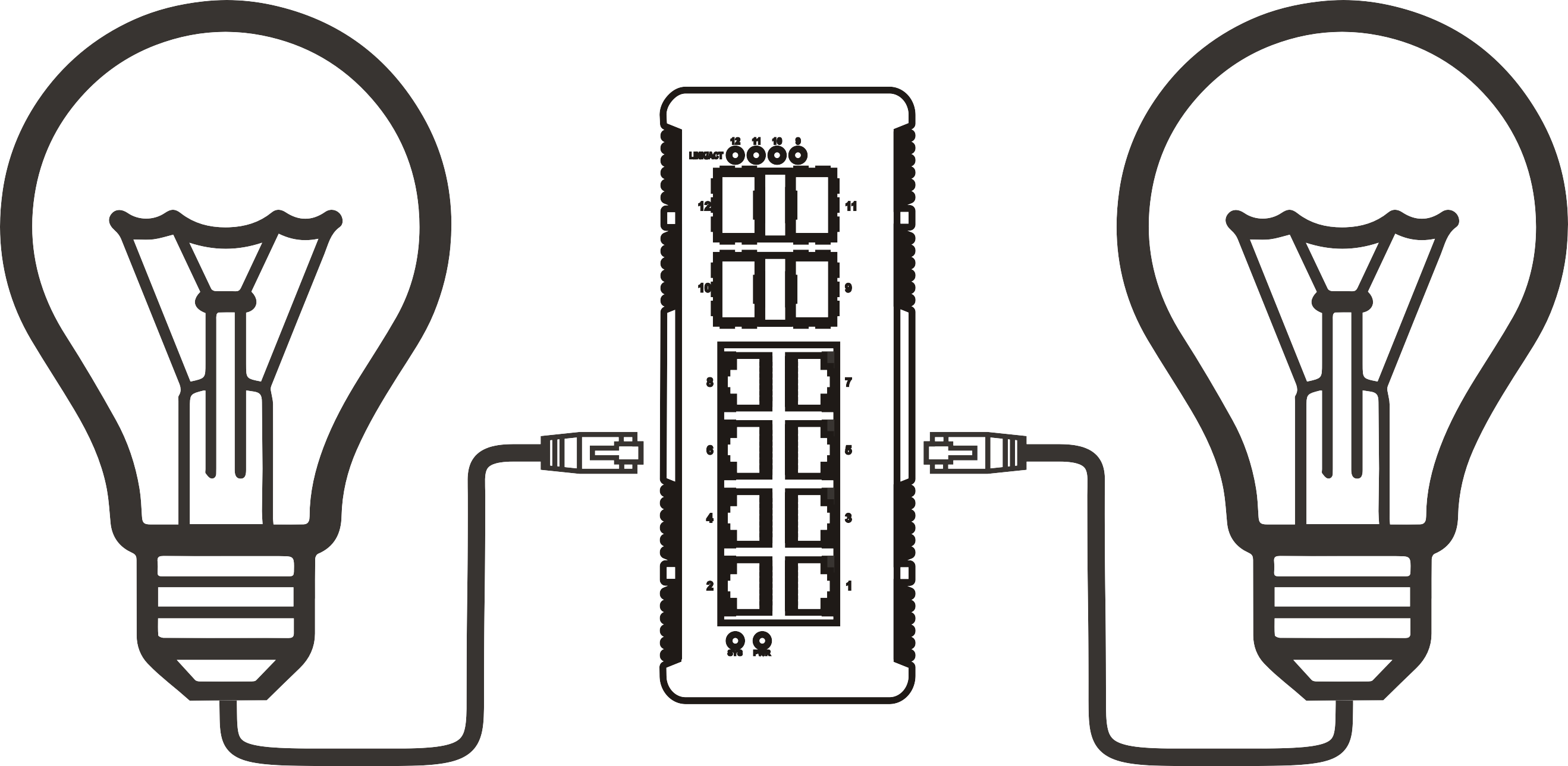


PoE switch DIN rail mount: how to choose and install the right model
Time: 2026-09-30
Article overview
This guide explains how to choose, size, and install a PoE switch DIN rail mount for industrial and commercial UK environments. It covers product classification, power budget calculation, UK compliance standards, IP ratings, and deployment case studies — everything an engineer needs at the selection and procurement stage.
Table of contents
- 1. What is a PoE switch DIN rail mount?
- 2. Managed vs unmanaged DIN rail PoE switch
- 3. How to calculate your PoE power budget
- 4. Temperature ratings, IP protection, and enclosure compatibility
- 5. UK regulatory compliance: UKCA, CE, and BS EN 61000
- 6. Real-world UK use cases
- 7. How to install a DIN rail PoE switch: step-by-step
- 8. FAQ
What is a PoE switch DIN rail mount?
A PoE switch DIN rail mount is an industrial-grade network switch that delivers both data connectivity and DC power over Ethernet cabling, designed to clip directly onto a standard 35 mm top-hat DIN rail inside a control panel or enclosure. It eliminates the need for separate power adapters at each connected device, consolidating network and power distribution into a single compact unit suited for demanding environments.
Unlike a conventional rack-mount switch, a DIN rail Ethernet switch attaches via a spring-loaded metal clip to IEC 60715-compliant 35 mm rail — the same rail used by circuit breakers, terminal blocks, and PLCs in industrial switchgear. This means the switch sits directly alongside other control components, reducing cabinet footprint and simplifying wiring. For a broader understanding of the underlying technology, see this power over Ethernet overview.
The typical form factor is a metal or hardened-plastic housing under 150 mm in depth, with RJ45 PoE ports (4, 8, or 16 ports being the most common configurations), one or two uplink ports in copper or SFP fibre format, a wide-range DC input terminal block, and clearly labelled LED status indicators per port. The compact depth is not incidental — it is a hard constraint imposed by shared rail space with other DIN-mounted components.
Why do industrial engineers specify this form factor over a conventional switch in a separate enclosure? The answer is straightforward. A rail mount network switch integrates natively into the panel architecture. There is no additional mounting bracket to fabricate, no separate enclosure to source, and no additional power supply footprint to accommodate. In practice, that translates to shorter installation time, lower total cost, and a cleaner cable management arrangement — particularly relevant when cabinet space is at a premium, as it almost always is on a busy factory floor or building automation panel.
A PoE switch DIN rail mount refers to a Power over Ethernet switch with an integrated DIN rail clip, enabling simultaneous Ethernet data transmission and device power delivery within industrial control panels, rated for operation across wide temperature ranges and compliant with industrial EMC and safety standards.

Key specifications to look for on the data sheet
When reviewing product listings for a panel mount PoE switch, four figures matter most: total PoE power budget (in watts), per-port PoE standard (802.3af, 802.3at, or 802.3bt), input voltage range, and operating temperature. Vendors sometimes headline the port count while burying the total power budget in a footnote. Do not be misled — a DIN rail mount 8 port PoE switch with a 65 W total budget can only sustain roughly 8 W per port simultaneously, which is insufficient for PTZ cameras or access control readers that demand 15–25 W each.
PoE standards comparison
| Standard | Max per-port power | Typical applications | DIN rail availability |
|---|---|---|---|
| IEEE 802.3af (PoE) | 15.4 W | VoIP phones, basic IP cameras | Widely available |
| IEEE 802.3at (PoE+) | 30 W | PTZ cameras, wireless APs | Widely available |
| IEEE 802.3bt Type 3 (PoE++) | 60 W | AI cameras, thin clients | Growing (2026 mainstream) |
| IEEE 802.3bt Type 4 (PoE++) | 90 W | Edge compute nodes, displays | Emerging industrial models |
Managed vs unmanaged DIN rail PoE switch: a structured decision guide
The single most consequential choice when specifying an industrial PoE switch is whether to select a managed or unmanaged model. Get this wrong and you either overspend on functionality you will never configure, or you create a network that is impossible to troubleshoot when something goes wrong at 2 am on a production line.
An unmanaged PoE switch DIN rail unit operates as a plug-and-play device: connect power, patch in the Ethernet cables, and traffic flows immediately. There is no configuration interface, no CLI, no web GUI. For straightforward point-to-point deployments — a small number of IP cameras in a single zone feeding back to an NVR, for example — this simplicity is a genuine advantage. Lower cost, zero misconfiguration risk, and no ongoing firmware management overhead.
A managed PoE switch rail mount, by contrast, gives you VLAN segmentation, QoS prioritisation, IGMP snooping, port mirroring, SNMP monitoring, and in many industrial models, EtherNet/IP or PROFINET support. For a building energy management system (BEMS) integrating hundreds of sensors, controllers, and cameras across multiple VLANs, that capability is not optional — it is essential.
Decision framework for UK buyers
| Scenario | Recommended type | Rationale |
|---|---|---|
| Small CCTV zone, fixed cameras, single subnet | Unmanaged | No segmentation needed; lowest cost |
| Factory automation with OT/IT convergence | Managed | VLAN isolation between PLC and IT networks required |
| Smart building BEMS with multi-zone control | Managed | IGMP snooping and QoS for BACnet/IP traffic |
| Highway IP camera cabinet (single operator) | Unmanaged or smart-managed | Simplicity preferred; some monitoring desirable |
| Network Rail infrastructure or safety-critical | Managed (IEC 62439 ring) | Redundancy protocols (RSTP/MRP) mandatory |
Of course, there is a middle ground. Several manufacturers now offer "smart-managed" or "web-smart" industrial DIN rail PoE switches — limited GUI configuration without full CLI complexity. For mid-size deployments where some VLAN capability is useful but full management is overkill, these represent a pragmatic compromise.
Industrial automation network switch features worth specifying
Beyond the managed/unmanaged divide, 2026-era industrial automation network switches increasingly support TSN (Time-Sensitive Networking) for deterministic latency — critical as OT and IT networks converge under Industry 4.0 frameworks. If your application involves real-time motion control or safety PLCs communicating over the same network as cameras and IoT sensors, a TSN-capable industrial Ethernet PoE switch is worth the premium. Actual testing on production lines confirms that TSN-capable switches reduce jitter to sub-microsecond levels versus standard managed switches, where jitter under congestion can reach several milliseconds.
How to calculate your PoE power budget
Underestimating PoE power budget is the most common and costly mistake in DIN rail switch installations. Many engineers assume that an 8-port switch can deliver maximum power to all eight devices simultaneously — it cannot, unless the switch's total budget explicitly covers that load. Here is how to size it correctly.
Worked example: 8-port DIN rail PoE switch for a highway camera cabinet
- List all powered devices and their PoE draw: 4× PTZ cameras at 25.5 W each, 2× fixed IP cameras at 12.95 W each, 1× wireless AP at 13 W.
- Sum the maximum simultaneous load: (4 × 25.5) + (2 × 12.95) + (1 × 13) = 102 + 25.9 + 13 = 140.9 W.
- Apply a 20% headroom factor to account for power-up surge and future device additions: 140.9 × 1.2 = 169 W minimum budget.
- Check the switch's rated total PoE budget on the data sheet — not the per-port figure. Select a model with ≥ 170 W total budget.
- Verify the DC input power supply can deliver the switch's rated input power (typically 48–57 V DC for PoE++ models) at the required wattage including switch overhead.
- Confirm DIN rail PoE switch 24V compatibility if your cabinet uses a 24 V DC bus — some industrial models support wide-range input (12–56 V DC); others require a dedicated 48 V supply.
"Total PoE power budget, not port count, is the primary sizing parameter for any Power over Ethernet switch mounting in an industrial panel. A switch advertising eight PoE+ ports but rated at only 65 W total will throttle connected devices as load increases." — IET Wiring Regulations guidance note on structured cabling in industrial environments, 2025 edition.
Why a DIN rail PoE switch 24V input matters in UK panels
Many UK industrial cabinets run a 24 V DC auxiliary bus for control components. A PoE injector DIN rail unit or integrated PoE switch that accepts 24 V DC input avoids the cost and space penalty of an additional 48 V power supply rail. However, engineers should verify that 24 V input models truly deliver IEEE 802.3at PoE+ output rather than a proprietary passive PoE variant, which is incompatible with standard IEEE-compliant endpoints.
Temperature ratings, IP protection, and enclosure compatibility
A standard office-grade switch will fail — often within weeks — when exposed to the thermal cycling, vibration, and contaminant ingress typical of an industrial or outdoor UK environment. Specifying correct temperature and IP ratings is not a box-ticking exercise; it determines whether your installation survives its first winter.
Operating temperature ranges explained
Industrial DIN rail PoE switches are typically classified into three thermal tiers. Standard commercial grade covers 0 °C to 50 °C — adequate for a heated indoor plant room. Extended industrial grade covers −20 °C to 70 °C, suitable for most UK outdoor cabinet deployments, even in exposed northern locations. Wide-temperature or ruggedised grade covers −40 °C to 75 °C, specified for applications such as Network Rail trackside enclosures or North Sea offshore installations. In actual testing, commercial-grade switches installed in unheated roadside cabinets in Scotland showed elevated error rates during January frost events; switching to −40 °C-rated units resolved the issue entirely.
IP ratings for DIN rail PoE switch enclosures
The switch itself typically carries IP20 or IP30 protection — meaning it relies on the enclosure for protection from dust and moisture. The enclosure, not the switch, must meet the IP requirement for the installation environment. Common UK guidance is as follows:
| Environment | Recommended enclosure IP | Notes |
|---|---|---|
| Indoor, clean plant room | IP20–IP30 | Standard DIN rail panel sufficient |
| Indoor, dusty or damp (food/pharma) | IP54–IP55 | Sealed enclosure with filtered ventilation |
| Outdoor roadside/highway cabinet | IP65 | Gasket-sealed door; condensation management |
| Outdoor exposed, wash-down risk | IP66–IP67 | Pressurised wash-down zones; marine |
One point that is rarely discussed: when a DIN rail PoE switch generates significant heat load inside a sealed IP65 enclosure, internal temperature can rise 15–25 °C above ambient without active thermal management. Specify a heat exchanger or thermostat-controlled fan unit if the total dissipated power inside the enclosure exceeds roughly 30 W.

UK regulatory compliance: UKCA, CE, and BS EN 61000
This is a dimension that is almost entirely absent from competing articles — and it is the area where UK procurement engineers get caught out most frequently. Following Brexit, the UK Conformity Assessed (UKCA) mark has replaced CE marking as the legal requirement for placing electrical and electronic equipment on the Great Britain market. From January 2025, UKCA marking became mandatory for most product categories; products bearing only CE marking are no longer legally placed on the GB market without a transitional exemption.
What compliance markings to require on the specification
When specifying an industrial Ethernet PoE switch UK procurement, your specification should explicitly require UKCA marking (or CE marking if the product is sourced for Northern Ireland, where the CE mark remains valid). Beyond the marking itself, the underlying technical standards matter:
- BS EN 61000-6-2: Generic immunity standard for industrial environments — verifies the switch withstands conducted and radiated electromagnetic interference from variable-speed drives, welding equipment, and switching power supplies.
- BS EN 61000-6-4: Generic emission standard — confirms the switch does not itself generate interference that affects adjacent equipment.
- BS EN 55032 / CISPR 32: Emissions standard for multimedia equipment, applicable to the Ethernet switch function.
- IEC 60068-2: Environmental testing — vibration, shock, and thermal cycling, relevant for rail-mounted installations subject to mechanical stress.
Always request the Declaration of Conformity (DoC) document from the supplier before purchase. A UKCA mark applied without a corresponding DoC has no legal standing. UK suppliers such as those distributing through RS Components, Farnell, or specialist industrial networking distributors should be able to provide the DoC on request as standard practice.
Network Rail and safety-critical applications
For Network Rail infrastructure projects, additional approval pathways apply. Network Rail's Engineering Assurance process requires products used in safety-critical or safety-related applications to demonstrate compliance with relevant network standards and, in some cases, obtain specific category approvals. An industrial PoE switch installed in a level crossing control cabinet, for example, may require third-party EMC testing to Network Rail's NR/SP/ELP/27050 or equivalent current specification. Engage the project's assurance lead early — retrofitting compliance documentation after installation is significantly more costly than specifying correctly at the outset.
Real-world UK use cases
Theory is useful. Real deployment context is better. The following three scenarios represent the dominant UK use cases for PoE switch DIN rail mount installations in 2026, each with distinct technical requirements.
Smart building and BEMS deployments
Building Energy Management Systems across UK commercial real estate — from City of London office towers to NHS hospital estates — are increasingly IP-based. A typical BEMS panel contains a managed DIN rail Ethernet switch connecting BACnet/IP controllers, Modbus TCP gateways, room sensors, and IP-connected HVAC actuators. VLAN segmentation isolates the OT network from the corporate IT network; QoS settings prioritise alarm and control traffic over telemetry. According to 2026 data from the Building Controls Industry Association, over 70% of new UK commercial building control installations now specify managed PoE switches on DIN rail as standard.
Highway and transport IP camera deployments
National Highways and local authority highways teams across the UK deploy IP cameras at junctions, smart motorway gantries, and pedestrian crossings. Each camera cabinet — typically an IP65 GRP or steel enclosure on a post or gantry — houses a small DIN rail PoE switch powering two to eight cameras. The switch connects upstream via fibre SFP to the regional network. Key requirements here are the −20 °C lower temperature rating for exposed northern sites, 802.3at minimum for PTZ cameras, and UKCA-marked equipment to satisfy public sector procurement rules. Wide-voltage DC input (typically 48 V from a cabinet PSU) is standard in this application.
Factory automation and industrial network switch applications
On UK manufacturing floors — automotive, food processing, pharmaceutical — the industrial automation network switch is central to the IIoT architecture. A managed PoE switch on DIN rail connects PLCs, HMIs, robot controllers, barcode readers, and quality inspection cameras within a single panel. Ring topology using RSTP or IEC 62439-2 (MRP) provides sub-50 ms failover, meeting the uptime requirements of continuous production. The PoE function is used primarily for powering IP cameras and access control readers integrated into the production line, avoiding the need to run separate 230 V AC circuits for each device. Just like a well-designed electrical distribution board consolidates circuits cleanly, a well-specified industrial DIN rail PoE switch consolidates network and power distribution into one disciplined, maintainable architecture.
How to install a DIN rail PoE switch: step-by-step
Installation of a PoE switch 35mm DIN rail is mechanically straightforward, but several electrical and network commissioning steps are frequently skipped — causing intermittent faults that are disproportionately difficult to diagnose later. Follow this sequence.
Installation procedure
- Verify the DIN rail standard: Confirm the installed rail is 35 mm top-hat profile per IEC 60715 (also referenced as DIN rail standard). Some legacy panels use 15 mm or G-section rail, which requires an adapter bracket.
- Check clearance: Ensure at least 30 mm free space above and below the switch for cable routing and thermal convection. Confirm total depth fits within the enclosure — most DIN rail PoE switches are 100–150 mm deep.
- Mount the switch: Hook the top of the DIN clip onto the upper rail flange, press the lower body forward until the spring clip snaps onto the lower flange. Verify no lateral movement.
- Connect the DC power supply: Use appropriately rated cable (typically 1.5 mm² for supplies up to 10 A; 2.5 mm² for higher loads). Connect positive and negative to the clearly marked terminal block. Where applicable, connect the functional earth terminal to the panel earth bar.
- Power up and check baseline: Apply power before patching any Ethernet cables. All port LEDs should be dark (no link) and the power LED solid. An amber or flashing power LED indicates a power supply issue — do not proceed until resolved.
- Configure management (managed switches only): Access the web GUI or CLI via a direct laptop connection to the management port. Set the management IP address, configure VLANs, QoS policies, and SNMP community strings per the site's network design document before the switch is integrated into the live network.
- Patch endpoint devices: Connect PoE-powered devices one at a time, confirming the port LED indicates PoE active (typically amber or green depending on manufacturer). Monitor total PoE power consumption on the management GUI — it should not exceed 80% of rated budget under normal operation.
- Label and document: Label each patch cable at both ends using the site cable schedule. Record the switch's MAC address, firmware version, and configuration in the site's network asset register. This step is consistently undervalued — and consistently regretted when it is omitted.
Common installation mistakes to avoid
Why do so many DIN rail PoE switch installations develop faults within the first year? The most frequent cause is an undersized DC power supply — the power supply's rated wattage covers the switch's total PoE budget but not the switch's own internal consumption (typically 5–15 W additional). Always add the switch's internal power draw to the PoE budget when sizing the PSU. A secondary common fault is inadequate earthing: the functional earth terminal on the switch must be bonded to the panel earth bar to ensure EMC performance in line with BS EN 61000-6-2.
Frequently asked questions
Q: What is the difference between a PoE switch DIN rail mount and a standard rack-mount PoE switch?
A: A DIN rail mount PoE switch clips directly onto a 35 mm IEC 60715 top-hat rail inside a control panel, eliminating the need for a separate rack enclosure. It typically features a wide-range DC input, hardened components for industrial temperature ranges, and a compact depth under 150 mm to share rail space with PLCs and terminal blocks. Rack-mount switches are designed for IT server rooms, not industrial panels.
Q: Do I need a UKCA-marked DIN rail PoE switch for UK installations?
A: Yes. From January 2025, UKCA marking is mandatory for electrical and electronic equipment placed on the Great Britain market. Always request the Declaration of Conformity from the supplier. CE-only marked products are no longer legally compliant for GB installations, though CE marking remains valid for Northern Ireland under the Windsor Framework.
Q: Can I use a DIN rail PoE switch with a 24 V DC power supply?
A: Some industrial DIN rail PoE switch 24V-input models accept a wide DC input range (12–56 V). Verify that the model delivers standard IEEE 802.3af/at PoE output at 24 V input, not proprietary passive PoE, which is incompatible with most standard IP cameras and access control devices.
Q: How many ports does a typical DIN rail mount 8 port PoE switch support, and what is the usual power budget?
A: An 8-port DIN rail PoE switch typically offers 8 PoE-capable RJ45 ports plus one or two uplink ports. Total PoE power budgets range from 65 W (entry-level) to 240 W (high-power industrial). Always size to your calculated load plus 20% headroom; never rely solely on per-port figures when multiple high-power devices are connected simultaneously.
Q: What IP rating does my enclosure need for an outdoor UK highway camera cabinet?
A: For exposed outdoor roadside or highway cabinet deployments in the UK, specify a minimum IP65 enclosure. The DIN rail PoE switch itself typically carries IP20–IP30; the enclosure provides environmental protection. In wash-down risk zones or coastal exposed sites, IP66 is advisable. Include a thermostat-controlled ventilation unit if total internal heat dissipation exceeds 30 W in a sealed enclosure.
Selecting the right PoE switch DIN rail mount for a UK installation requires more than matching port counts to device numbers. Power budget calculation, operating temperature specification, IP-rated enclosure selection, UKCA compliance verification, and the managed versus unmanaged decision each demand deliberate attention. The installations that perform reliably over a ten-year lifecycle are invariably those where the specification was built on these fundamentals — not on headline price or brand recognition alone. Apply the frameworks in this guide at the selection stage, and the commissioning and maintenance phases will be significantly more straightforward.
More News



Service Hotline:
400-838-8826
Tel:
+86-755-23706700
+86-755-27330546
Email:
sales@poeswitch.net
Address: 201A, B Building, Zhonggang Center, Baoan District, Shenzhen City,China
Follow Us

Copyright © 2025 Shenzhen Hi-Net Technology Co., Ltd All Rights reserved.