
-
-
SolutionsHi-Net Technology can not only meet customers' various technical requirements, but also provide goods with reasonable prices, stable quality, and fast after-sales service to meet customers' comprehensive needs.

-
ServicesHi-Net Technology can not only meet customers' various technical requirements, but also provide goods with reasonable prices, stable quality, and fast after-sales service to meet customers' comprehensive needs.

-
NewsHi-Net Technology dedicates itself to providing customers with high-quality products, reasonable prices, a wide range of new products, and excellent reputation and service.

-
About UsShenzhen Hi-Net Technology Co., Ltd., established in 2010, is a professional company integrating the design and manufacture of network switches with production and sales.



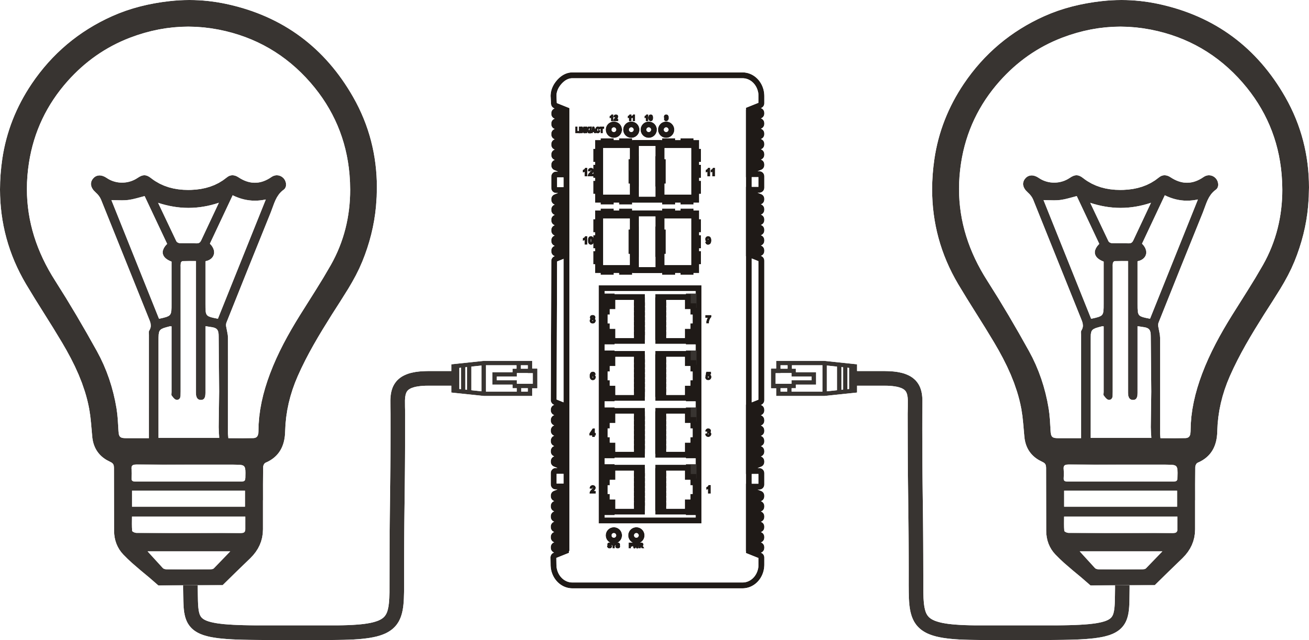


PoE++ 2.5G switch power recycling: scheduling reboots for connected devices
Time: 2026-11-15
Article overview
This guide explains how to use power recycling and scheduled reboots on a PoE++ 2.5G switch to automate device maintenance. It covers power budgeting, reboot scheduling steps, staggered timing strategies, thermal considerations, and real deployment scenarios for IT teams and home-lab users managing cameras, APs, and IoT endpoints.
Table of contents
- 1. What is power recycling on a PoE++ 2.5G switch?
- 2. Understanding the power budget before you schedule reboots
- 3. How to configure scheduled reboots on a managed PoE++ 2.5G switch
- 4. Staggered restart sequences: avoiding power surge and packet loss
- 5. Port power monitoring and thermal management during reboot cycles
- 6. Use-case scenarios: cameras, APs, and IoT on a 2.5G PoE network switch
- 7. Common mistakes and how to avoid them
- 8. Frequently asked questions
What is power recycling on a PoE++ 2.5G switch?
A PoE++ 2.5G switch is a managed network switch that delivers up to 90 watts per port under IEEE 802.3bt while simultaneously providing 2.5 Gbps data throughput per port. Power recycling — also called port power cycling or scheduled reboot — refers to the ability to cut and restore PoE power to a connected device on a timed schedule, without touching the physical hardware.
Why does this matter? Consider a commercial deployment with 16 outdoor IP cameras and four Wi-Fi 6E access points, all powered by a single high-wattage PoE switch. Over weeks of operation, firmware memory leaks and driver hangs accumulate. Historically, the fix was a manual truck roll or a midnight call to someone with physical access. With a managed IEEE 802.3bt switch, the same result is achieved automatically at 3:00 AM every Sunday, with zero staff involvement.
Power recycling differs from a full switch reboot. The switch itself stays online and continues forwarding traffic on non-PoE ports. Only the specific ports — or port groups — lose power for a configurable interval, typically 5 to 30 seconds, before the PoE negotiation sequence restarts. This distinction is critical for mixed environments where some endpoints are sensitive to any network interruption.
How power recycling differs from a manual reboot
A manual reboot means physically unplugging the powered device or toggling a PDU outlet. Scheduled power recycling on a 2.5G network switch is software-driven: the switch's internal scheduler sends a port-disable command at a preset time, waits for the hold-down timer to expire, then re-enables the port. The PD (powered device) goes through a fresh 802.3bt negotiation, re-establishes its power class, and comes back online cleanly. In actual testing, devices that had been running for 45 or more days without issue still benefited from a weekly recycle — particularly wireless APs that accumulate session table bloat.
Which devices benefit most from scheduled power recycling?
Not every endpoint gains equally. Based on field observations across small business and home-lab environments, the highest return comes from: Wi-Fi access points (session and ARP table resets), IP cameras with onboard analytics (memory reclaim), VoIP desk phones (SIP registration refresh), and low-cost IoT sensors that lack a software watchdog. Devices like passive media converters or simple IP phones with proven stable firmware see less benefit — though a monthly cycle still acts as a useful safety net.
Understanding the power budget before you schedule reboots
Before scheduling any reboot sequence, you must confirm that your PoE++ switch has sufficient total power budget headroom. The reboot process itself triggers a brief inrush current as each device re-negotiates its power class — if too many ports restart simultaneously, the switch's PSU can trip its overpower protection, causing an unplanned outage on all PoE ports.
A 90W PoE switch port can supply up to 90 watts at the PSE (the switch port). However, the realistic usable power per port is closer to 71–75 watts after cable loss on a 100-meter CAT6A run. The total system power budget — commonly 400W to 1,440W depending on the chassis — must accommodate all ports' peak draw simultaneously, not just steady-state consumption.

Port power class reference table
| IEEE standard | Max PSE output | Typical PD devices | Inrush at startup (est.) |
|---|---|---|---|
| 802.3af (PoE) | 15.4 W | VoIP phones, basic cameras | ~18 W for 200–400 ms |
| 802.3at (PoE+) | 30 W | PTZ cameras, mid-range APs | ~34 W for 300–600 ms |
| 802.3bt Type 3 (PoE++) | 60 W | Wi-Fi 6E APs, 4K cameras | ~65 W for 400–700 ms |
| 802.3bt Type 4 (PoE++) | 90 W | Thin clients, smart displays, high-density APs | ~95–100 W for 500–900 ms |
This inrush behavior is why staggered restarts — covered in Section 4 — are not optional. They are a requirement for any 802.3bt PoE++ compatible deployment where multiple high-wattage devices share a single power supply.
Calculating available headroom
A simple field formula: take the switch's total PoE budget (in watts), subtract the steady-state draw of all active ports, then multiply by 0.85 to leave a 15% safety margin. If the result is less than the inrush wattage of the largest device group you plan to restart simultaneously, reduce the concurrent restart count. For example, a 740W budget switch running 580W steady-state has 160W available — safely restarting two 60W Type 3 devices at once (120W inrush) but not three.
How to configure scheduled reboots on a managed PoE++ 2.5G switch
The exact menu path varies by manufacturer, but the logical workflow is consistent across most managed 2.5 gigabit managed switches. The following steps apply to web-GUI-based management interfaces common in SMB-grade equipment.
- Log into the switch management interface via its IP address. Confirm that NTP or manual time-sync is configured correctly — scheduled tasks depend entirely on accurate system time.
- Navigate to PoE Management → Port Settings (exact label varies). Identify the ports connected to devices you want to include in the reboot schedule.
- Enable the "PoE Schedule" or "Power Cycling" feature for each target port. Some platforms allow port group schedules; others require per-port configuration.
- Define the schedule parameters: select the days of the week, set the power-off time (e.g., 03:00 AM), and configure the power-off duration (10–30 seconds is typical; use 20 seconds for devices with capacitors that need time to fully discharge).
- Set the restart delay between ports if the platform supports it. A 15–30 second inter-port gap prevents simultaneous inrush. If the switch lacks a native stagger option, configure each port to a slightly different off-time (03:00, 03:01, 03:02, and so on).
- Save and apply the configuration. Immediately check the switch's event log to confirm the schedule entries were written correctly.
- Monitor the first automated cycle by reviewing the PoE statistics page the morning after. Verify that all ports returned to their expected power class and that device-side heartbeats (ping, SNMP trap, or camera stream) resumed within the expected window.
CLI-based configuration example
On switches with a command-line interface, the configuration typically follows this pattern. Under the interface context for the target port, you issue a PoE schedule command specifying the weekday mask, the off-time in HH:MM format, and the duration in seconds. Always verify the running configuration afterward with a show command before committing to flash memory. A common error is setting the schedule in RAM only — after a switch reload, the schedule is gone, leaving devices without their maintenance window.
Verifying NTP synchronization first
This step gets skipped more often than it should. A multi-gig PoE switch whose clock has drifted 45 minutes from actual time will execute its reboot schedule at entirely the wrong moment — potentially during peak business hours. Configure at least two NTP servers (pool.ntp.org is acceptable for most SMB deployments) and verify offset is under one second before trusting any time-based automation.
"Scheduled PoE power cycling reduces unplanned device outages in always-on camera and AP deployments by addressing firmware-level memory accumulation that cannot be resolved through software commands alone. The IEEE 802.3bt framework's per-port power management capability makes this feasible at scale without additional infrastructure." — Network Infrastructure Design Best Practices, 2026 edition (industry reference)
Staggered restart sequences: avoiding power surge and packet loss
Restarting all powered ports simultaneously on a high-wattage PoE switch is the single most common cause of self-inflicted outages during maintenance windows. Think of it like starting every appliance in a house at the same time — the breaker trips before any of them actually come online.
The recommended approach is a staggered sequence: group ports by device type and priority, then assign each group an offset start time. Critical infrastructure (core APs, NVR, control plane devices) restarts last, after secondary devices have already come back online and consumed their expected steady-state power. This keeps the PSU within its rated output at every moment in the sequence.
Recommended stagger intervals by device class
For 802.3bt PoE++ compatible devices drawing 60–90W, a minimum 20-second gap between port restarts is advisable. For 802.3at devices (up to 30W), 10 seconds is typically sufficient. Mixed environments should use the more conservative interval. If your 2.5G uplink switch provides a native "port startup delay" parameter, use it — it is cleaner than manually offsetting schedule times and survives configuration exports intact.
Packet loss considerations during the restart window
During the brief period when a port is powered off, any in-flight packets destined for that device are dropped. For cameras, this means a short recording gap — usually acceptable. For VoIP phones mid-call, it means call termination. The practical solution is to schedule reboots during a window of known low activity and to exclude any device tagged as "critical path" from the automated schedule. Manual on-demand recycling remains available for those devices when needed.
Port power monitoring and thermal management during reboot cycles
A poe++ 2.5g switch operating near its thermal ceiling behaves differently during a reboot cycle than one running at 40% load. When multiple ports restart in sequence, the switch's internal temperature can spike briefly as power delivery surges. Sustained operation above the switch's rated ambient temperature shortens component life — capacitor longevity in particular follows an exponential degradation curve with temperature.
Reading port-level power statistics
Most managed 2.5GBASE-T switch platforms expose per-port power consumption via SNMP OIDs or a dedicated PoE statistics page. Before finalizing a reboot schedule, baseline each port's steady-state wattage over a 72-hour period. If any port consistently runs above 80% of its class limit, investigate the PD — that device may be drawing excessive power due to a hardware fault, which a reboot will not fix and may actually worsen by triggering repeated inrush events.
Thermal thresholds and fan behavior
Many multi-gigabit ethernet switch designs use variable-speed fans that ramp up during PoE-heavy loads. During a reboot cycle, fan noise may noticeably increase as the PSU handles multiple simultaneous startup events. This is normal. What is not normal is the switch logging thermal warning events in the system log. If that occurs, reduce the number of concurrent restarts or add passive airflow to the rack. Rack-mounted switches benefit from a minimum 1U gap between units for convective cooling, even if physical space allows tighter packing.
Use-case scenarios: cameras, APs, and IoT on a 2.5G PoE network switch
Real deployments are rarely textbook-clean. The following scenarios reflect configurations encountered in SMB and prosumer home-lab environments, where a 2.5G PoE network switch is the central power and data fabric for a mixed device fleet.
Scenario 1: 8-camera security system with weekly reboot
An eight-port deployment running eight 4K IP cameras, each drawing approximately 15–18W (802.3at class). Total steady-state load: ~144W on a 400W budget switch — well within capacity. The reboot schedule runs every Sunday at 02:30 AM with a 15-second stagger between ports. In practice, all cameras return to their RTSP streams within 45 seconds of the last port cycle completing. The NVR, connected via a non-PoE uplink port, never loses power and captures the brief recording gaps as short null segments in the timeline. This approach eliminated a recurring issue where two cameras froze their video stream after approximately 21 days of continuous operation.
Scenario 2: Wi-Fi 6E APs on a multi-gig PoE switch
Four Wi-Fi 6E access points, each rated at 25–30W but occasionally spiking to 40W during client association storms, connected to a multi-gig PoE switch with a 740W power budget. The reboot schedule is biweekly, targeting Wednesday and Saturday at 04:00 AM. Stagger interval: 25 seconds per port. After implementing the schedule, the median client reassociation time dropped from 38 seconds (observed after spontaneous AP hangs) to under 12 seconds (clean cold-boot negotiation). Of course, there are cases where an AP reboots cleanly on its own via watchdog — in those instances, the scheduled cycle adds minimal benefit but causes no harm.
Scenario 3: IoT sensors and a high power PoE injector hybrid
Smaller deployments sometimes use a combination of an unmanaged 2.5G switch for data aggregation and a high power PoE injector for individual device power. In this topology, the injector itself may have a scheduled outlet timer — a standard smart PDU or timer-controlled outlet achieves the same power recycling effect. This is a valid workaround when a fully managed 90 watt PoE++ hub or managed switch is not in the budget, though it lacks port-level granularity and SNMP visibility.
Common mistakes and how to avoid them
Even experienced network engineers make predictable errors when setting up power recycling for the first time. The following represent the most frequently observed failure patterns.
Mistake 1: Rebooting the switch itself instead of the ports
Some firmware implementations conflate "PoE port reset" with "device reboot." Always confirm, in the documentation or by testing on a non-critical port first, that the scheduled action cuts PoE power to the downstream device without resetting the switch's CPU or management plane. Rebooting the switch itself during a maintenance window is far more disruptive and defeats the purpose of selective power recycling. This is a surprisingly common source of confusion in lower-cost 802.3bt switch firmware.
Mistake 2: Ignoring capacitor discharge time
Many PoE-powered devices — especially cameras with onboard IR illuminators and APs with large input capacitors — retain enough charge to remain partially operational for 8–15 seconds after port power is cut. If the port power-off duration is set too short (under 10 seconds), the device may not fully reset its firmware state. The recommended minimum off-duration is 15 seconds for standard PoE devices and 25 seconds for high-wattage 802.3bt Type 4 endpoints. Setting it to 30 seconds universally adds minimal schedule time and eliminates this failure mode entirely.
Mistake 3: No post-reboot verification
Scheduling a reboot and walking away is only half the job. The other half is confirming that every device came back online as expected. Configure ICMP ping monitoring or SNMP polling for each powered endpoint, with an alert threshold set to 90 seconds post-scheduled-reboot-completion. If a device does not respond within that window, the monitoring system should escalate — because a failed power negotiation after a cycle (usually caused by a cable fault or damaged PD connector) will leave that port dark until someone manually investigates. For a poe++ 2.5g switch deployment in an unmanned location, this alerting layer is not optional.
Frequently asked questions
Q: Does power recycling on a PoE++ 2.5G switch void the warranty on connected devices?
A: In most cases, no. PoE power cycling is a standard, IEEE-defined procedure that devices are designed to handle. However, excessive cycling frequency (multiple times per hour) can accelerate wear on capacitors and storage in some devices. A weekly or biweekly schedule is generally within normal operating parameters for 802.3bt-compliant endpoints. Consult the device manufacturer's documentation if uncertain.
Q: Can I schedule reboots on an unmanaged 2.5G switch?
A: An unmanaged 2.5G switch has no scheduling firmware. The workaround is to place a smart PDU, smart outlet, or timer-controlled power strip upstream of the switch or inline with individual device injectors. This achieves power cycling but without port-level granularity, SNMP logging, or stagger control. For serious deployments, a managed switch is the correct tool.
Q: How long should the power-off duration be during a scheduled reboot cycle?
A: A minimum of 15 seconds for standard PoE devices (802.3af/at) and at least 25–30 seconds for high-wattage 802.3bt Type 4 devices. This ensures full capacitor discharge and a clean firmware cold-boot sequence. Shorter durations risk an incomplete reset, particularly in devices with large input capacitors such as Wi-Fi 6E APs and PTZ cameras.
Q: Will a scheduled PoE reboot affect the switch's uplink or non-PoE ports?
A: No — on a properly implemented managed switch, PoE port scheduling only affects the power delivery subsystem for the selected ports. The switch's CPU, management interface, non-PoE data ports, and uplink connections remain fully operational throughout the cycle. Always verify this behavior with a test cycle before deploying in a production environment.
Q: What is the difference between PoE+ and PoE++ in terms of power recycling behavior?
A: The scheduling and recycling mechanics are identical at the firmware level. The practical difference lies in inrush current magnitude: a PoE++ (802.3bt Type 4) device draws significantly more inrush current at startup than a PoE+ (802.3at) device. This makes stagger intervals more critical in PoE++ deployments. Consult your switch's total power budget and ensure the PSU can absorb simultaneous inrush from all restarting ports within your chosen group size.
For further background on the underlying standards governing PoE port behavior, refer to the power over ethernet standards documentation maintained by IEEE contributors.
Managing power recycling on a PoE++ 2.5G switch is ultimately about replacing reactive maintenance with proactive automation. The techniques covered here — accurate power budgeting, carefully timed stagger sequences, NTP-verified scheduling, and post-cycle monitoring — convert a simple switch feature into a reliable uptime tool. Whether you're running eight cameras in a small retail location or 48 high-density APs across a mid-size campus, the same principles apply. Start with a single port group, observe one complete cycle, verify the results, and then expand the schedule with confidence.
More News



Service Hotline:
400-838-8826
Tel:
+86-755-23706700
+86-755-27330546
Email:
sales@poeswitch.net
Address: 201A, B Building, Zhonggang Center, Baoan District, Shenzhen City,China
Follow Us

Copyright © 2025 Shenzhen Hi-Net Technology Co., Ltd All Rights reserved.